


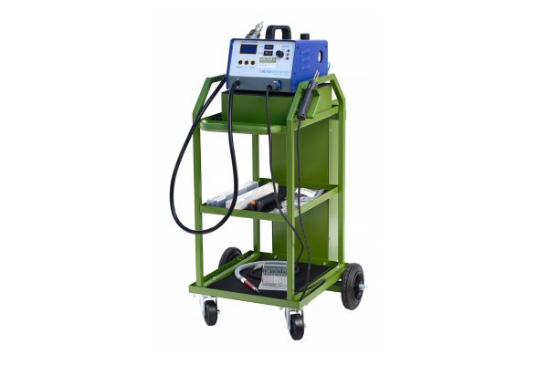


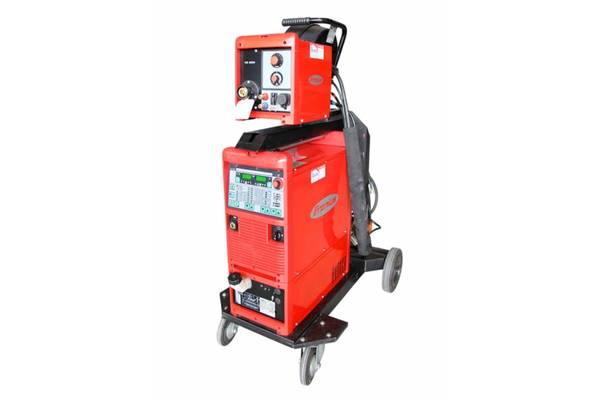


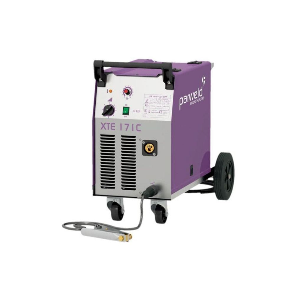

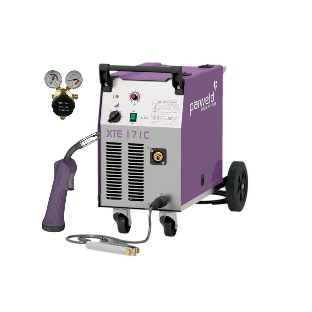


PARWELD XTE 171C MIG WELDER
-
Prices Exclude Tax
Brand: Parweld Type: Mig Welder
Parweld XTM 171C MIG Welder for Automotive & Fabrication, UK
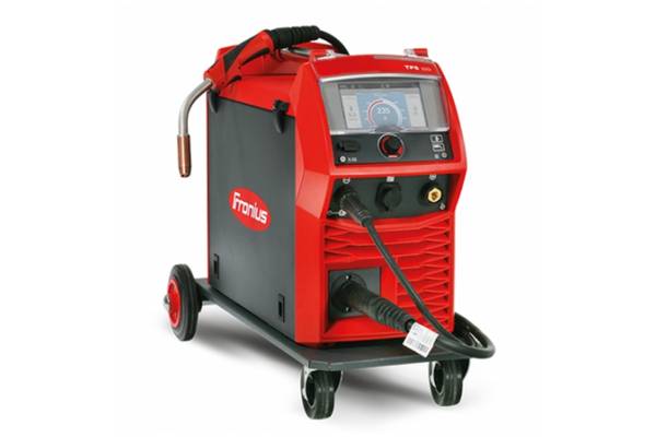
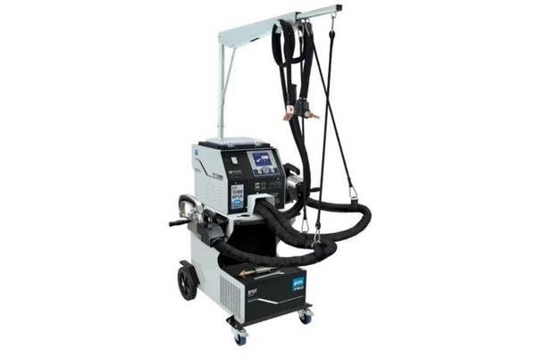
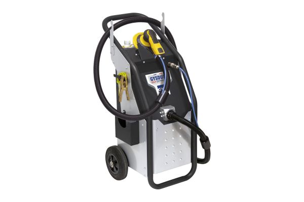
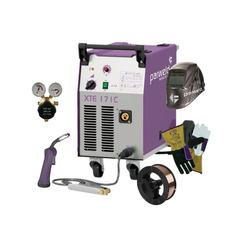
Designed for automotive and light fabrication use. It has a metal wire feed unit (compared to plastic on many manufacturers) and professional euro adapter torch connection. The case is sturdy and well made and fits full-size bottles. Quality rubber wheels enable easy manoeuvrability. It comes with a comprehensive return to base 2-year warranty.
Built to last, the PARWELD XTE 171C MIG WELDER is the perfect tool for automotive and light fabrication tasks. With a sturdy metal wire feed unit and professional euro adapter torch connection, it provides reliable performance and effortless welding. The rubber wheels ensure easy manoeuvrability, while the full-size bottle compatibility makes it a convenient choice for professionals.
WHY BUY FROM BWS?


Why Buy From BWS
30 years experience and our own mobile team of welding engineers offering advice, service, repairs and training means you can buy with confidence knowing you have a great team behind you supporting you!
Collections: 240V MIG WELDERS, Best Selling Products, MIG WELDERS, MIG WELDING, Newest Products, PARWELD, PARWELD MIG WELDERS
Operation
- Switch on the machine using the main ON/OFF switch. The green LED will light, and the voltage selector switch becomes active.
- Select your voltage by turning the “VOLTAGE SELECTOR” to one of the available settings.
- Check drive rolls and torch parts to ensure they match the wire size and type being used.
- The optimum wire feed pressure will vary depending on wire type, size, and condition. As a general rule:
- Hard wires may require slightly greater pressure.
- Soft or aluminium wires require less pressure than factory settings.
- If wire slips, increase tension slightly.
- If wire kinks or birds-nests, reduce pressure gradually until feed is smooth.
- If replacing wire, loosen the adjustment knob about half a turn and refit the wire. Feed forward until a slight waviness appears in the exposed wire — too much tension indicates over-pressure.
Feeding the Welding Wire
- When the trigger is pulled, both the drive motor and electrode are LIVE. Always treat the torch as live until several seconds after releasing the trigger.
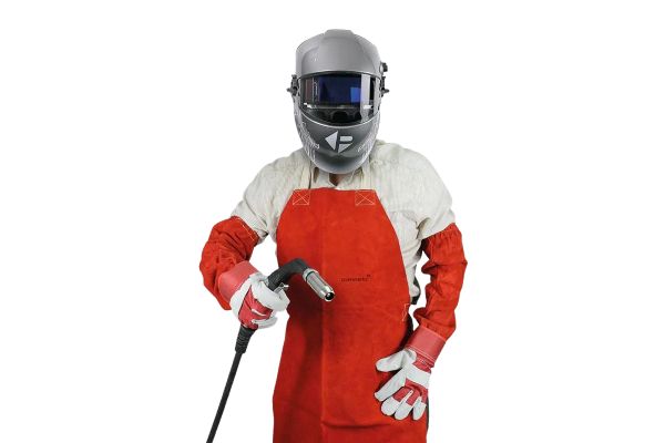
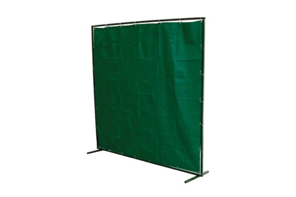
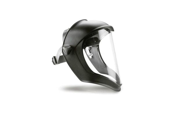
- Safety Warning: When using an open-arc process, correct eye, head, and body protection must always be worn.
- Position the wire at the joint, lightly touching the workpiece, and begin welding.
- Hold the torch 8–10 mm from the contact tip to the workpiece and maintain a steady travel speed.
- When stopping, release the trigger, pull the torch away, and close the gas valve (if fitted).
- When welding is complete, purge gas briefly to release pressure and then switch off the machine.
Optimising Weld Parameters
Note: The following settings are guidelines only. Adjustments may be required based on material thickness, wire type, joint design, shielding gas, and torch angle. Always produce test welds before proceeding.
Material Thickness and Amperage
- Convert material thickness to amperage using the rule: 0.25 mm ≈ 1 Amp
Example: 3.2 mm steel ≈ 125 A. - Select wire size based on amperage:
- 40 – 145 A → 0.8 mm wire
- 50 – 180 A → 1.0 mm wire
- 75 – 250 A → 1.2 mm wire
- Recommended wire feed speeds per amp:
- 0.8 mm → 0.05 m/min per Amp
- 1.0 mm → 0.04 m/min per Amp
- 1.2 mm → 0.025 m/min per Amp
-
Voltage setting:
- Low voltage → wire stubs into work
- High voltage → unstable arc with spatter
Proper setup of amperage, wire feed, and voltage ensures optimum weld penetration, minimal spatter, and a clean bead appearance.