


5 Checks To Do Before You MIG Weld
MIG/MAG welding is widely used in automobile repair shops and over many years of repairing and teaching welding, these are the 5 checks I would recommend you do before you even weld on the vehicle.
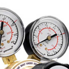
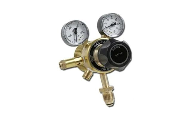
1, Check Your Gas And Gas Flow.
When steel welding on automobiles the gas used is extremely important as the gas gives certain characteristics to your weld seam and profile.In Europe we tend to MAG weld, that is our gases have Co2 and Oxygen in a mix that is typically 95% Argon with 3% Co2 and 2% Oxygen. This mix can also vary from country to country as for instance, Germany is 97.5% Argon. What you need to understand here is that the gas is ACTIVE , it serves a purpose, it’s the A in MAG. Its purpose is to make your weld pool hot and more liquid, which is fine. Therefore the percentage of the Co2 and oxygen used for automotive use is important.
Argon Ar
This is the main gas used in the mix and basically this is just a shield gas, it stops the atmosphere from attacking your molten pool. When atmosphere attacks a molten pool you get lots of porosity pinholes and the weld is very narrow and concentrated. The Argon gas stops this and allows the liquid / molten metal to spread like a normal liquid would when poured onto the floor, meaning wide pools with little penetration.
Argon also reduces spatter and improves arc stability. Most modern MIG MAG welding equipment is designed to weld with Argon mix gases.
Carbon Dioxide C02
Carbon Dioxide (CO2) is the most common of the reactive gases used in MIG welding and the only one that can be used in its pure form without the addition of an inert gas. Pure Co2 creates heat in the pool allowing for deeper penetration and a stiff arc which is good for positional welding. High carbon dioxide has a tendency to create globules and increased spatter in the arc process. It also can only be used in dip transfer mode.
Oxygen O2
Is also reactive gas it is added to provide weld pool fluidity, “wetness” and arc stability, provide reduce spatter it also increases the welding speed.
Today I was at a workshop and the welding equipment had fitted 15% mix gas bottles. They had been supplied incorrectly. The 15% mix is for fabrication and is very hot for automotive use, no wonder the technicians were complaining that it was blowing holes when trying to weld that quarter panel.
The other important factor in this is the FLOW. Think about it, the more flow you have the more Co2 and Oxygen is in your weld pool, recommended flow is 10-14 Litres Per Minute (LPM). I always recommend for automotive use go to the bottom of this range, especially when trying to MAG Steel weld a Peugeot quarter panel.
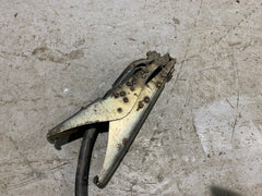
2, Check Your Earth Clamp.
Current flow is misunderstood when welding, the general view is that the welding current comes from the welding torch and returns back to the machine via the earth clamp. Some welders even call the earth clamp the “return”. This is incorrect, when we talk about current we actually mean Electron flow and this flows from the earth clamp and returns back to the machine via the welding wire. The welding wire is the pinch point for the current and so this is where the wire will blow up.
A loose and dirty earth clamp creates resistance to current (electron) flow and so will heat up when welding. This can vary considerably the current available at the wire pinch point creating arc instability.
Think about it, if you are only welding at 80 amps and an inch into your weld your earth clamp heats up reducing you current available to 60 amps this will affect your weld pool heat and even create less penetration. This fluctuation can also make the arc unstable, possibly creating spatter.
Your earth clamp should be clean and always cool to the touch. After you have done a little welding, feel the clamp, if its warm or hot something is wrong and it needs rectifying.
The earth clamp is even more important when MIG braze welding and also aluminium welding. MIG Braze due to the lower welding currents used and aluminium due to the higher wire feed speeds. Losing welding current for a second can create major problems that the welder will feel at the torch.
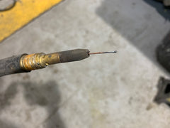
3, Check Your Contact Tip.
The contact tip has two main functions:
1. To ensure smooth feeding of the welding wire.
2. To ensure current is transferred from the wire and returned to the machine.
A loose contact tip does exactly the same thing as a poor earth clamp it creates instability of the welding arc which you will feel in your torch when welding.
The contact tip size is also important, the hole in the tip should allow smooth feeding of the wire yet also transfer the current smoothly. As a welding tip heats up during welding the copper expands and this, in turn, narrows the hole that the wire is feeding through causing the wire to be pinched and possibly slowing the wire feed down. This is natural hence contact tips are sized for the correct wire taking into consideration this expansion. A loose tip will heat up faster and also suck some of your welding current, again at low currents used in automotive welding this will create problems. A large or oversized hole creates its own problems, the welding wire can move about in the contact tip hole creating irregular current contact and movement of the wire possibly increasing spatter and weld position.
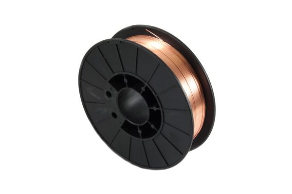
Thin welding wires (typically 0.6mm) have a severe problem with the helical coil, this is the natural curving of the wire as it is manufactured and then wound onto the wire drum. This spooling creates a snaking of the wire as it is drawn off the spool by the drive rollers and fed into the torch. The thinner the wire and the smaller the spool, the more of this snaking of the wire.
The effect of this is the wire moves around as it exits from the torch, a tight contact tip hole reduces this and enables you to feed your wire into the weld pool more smoothly and quickly.
A large hole enables the wire to move about creating more spatter and making it more difficult to get an instant weld pool. This is essential in automotive welding as it can create higher weld profiles that need grinding, poor weld appearance and enable blowing holes in the panel easier.
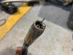
4, Check Your Nozzle.
Your nozzle is important its the main part that controls gas flow. The gas nozzle and its size should be correct for what you want to weld. In automotive use, we would recommend no larger than the 150 sizes.
Also If you choose a nozzle that is too narrow for the application or if the diffuser becomes clogged with spatter, for example, there might be too little shielding gas getting to the weld pool. Likewise, a poorly designed diffuser might not channel the shielding gas properly, resulting in turbulent, unbalanced gas flow. Both scenarios can allow pockets of air into the shielding gas and lead to excessive spatter porosity and weld contamination.
Always clean your nozzle!
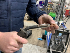
5, Check Your Wire Tension.
Finally, a quick check of wire tension is important (see 3) as the feeding needs to take into consideration the closing up of the contact tip hole during welding.To test this:
* Place your forefinger and thumb onto the wire at the torch and press lightly.
* Press the torch trigger and let the wire feed through you finger and thumb.
* Gradually increase your finger and thumb pressure until you can stop the wire.
* If you can stop the wire too easily, then increase tension at the rollers.
* If you cant stop the wire or its spools off (birds nests) at the rollers then you have too much tension and need to reduce it.
Doing these simple, quick tests BEFORE you weld will greatly improve your weld quality and the appearance of your welds.
Happy Welding!
Leave a comment
Comments will be approved before showing up.